Opinion | Feb. 7th, 2025
David Carter
Pressure Product Line Manager
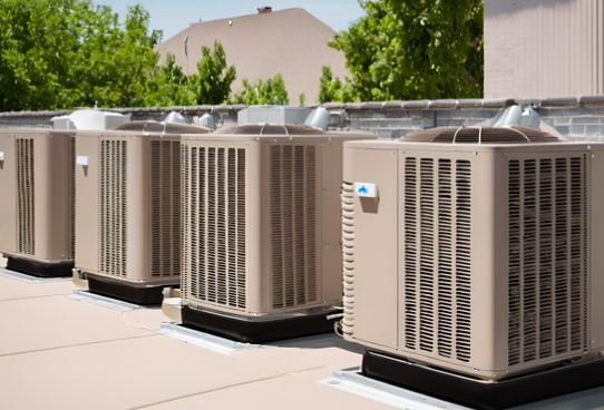
In the realm of industrial automation, pressure transmitters serve as critical devices, responsible for the precise conversion and transmission of pressure signals. They are widely utilized in sectors such as petrochemicals, power generation, and metallurgy. However, pressure transmitters, over extended periods of operation, are prone to various faults, with zero drift and signal interference being particularly prominent.
These issues can severely impact measurement accuracy and system stability. A thorough analysis of these faults, along with mastering effective solutions, is crucial for ensuring smooth industrial production.
Manifestations and Impact of Zero Drift:
Zero drift refers to the deviation of the output signal from its initial zero point when there is no pressure input or when the pressure is constant. This phenomenon can lead to measurement errors, affecting the accuracy and reliability of the entire control system. In chemical production, precise monitoring of material pressure is essential. Zero drift may cause the control system to misjudge material pressure, leading to improper adjustments of production parameters, which can result in product quality issues or even safety incidents.
Causes of Zero Drift:
Environmental Factors: Temperature variations are a common environmental factor causing zero drift. The electronic components inside a pressure transmitter are sensitive to temperature changes, which can alter their characteristic parameters, leading to zero shift. For instance, in high-temperature environments, resistance values may change, affecting the circuit’s output voltage. Additionally, humidity changes can corrode circuit boards inside the transmitter, affecting its electrical performance and causing zero drift.
Mechanical Vibration: Industrial environments often have significant mechanical vibrations. Prolonged exposure to such conditions can cause the internal structure of a pressure transmitter to loosen or shift, altering the sensor’s zero position. For example, if the connection between the sensitive element and the elastic element loosens, it may introduce additional stress when no pressure is applied, resulting in zero drift.
Component Aging: Over time, the electronic components inside a pressure transmitter may degrade, leading to performance deterioration. Changes in capacitance value or transistor amplification factors can contribute to zero drift.
Solutions for Zero Drift:
Temperature Compensation: To mitigate the impact of temperature variations on zero drift, temperature compensation techniques can be employed. By integrating a temperature sensor within the pressure transmitter, environmental temperature can be monitored in real-time, and output signals can be compensated accordingly. For example, software algorithms can process data from the temperature sensor to calculate the impact of temperature changes on the zero point and adjust the output signal.
Mechanical Reinforcement: To address zero drift caused by mechanical vibrations, mechanical reinforcement of the pressure transmitter is necessary. During installation, use vibration-damping mounts or pads to reduce vibration transmission to the transmitter. Regularly inspect the internal structure to ensure all components are securely connected, and tighten any loose parts promptly.
Regular Calibration: Regular calibration of pressure transmitters is an effective means to address zero drift. Establish a reasonable calibration schedule based on the operating environment and precision requirements. During calibration, use high-precision standard pressure sources to adjust the zero point and range of the transmitter, ensuring its output signal matches the actual pressure value.
Manifestations and Impact of Signal Interference:
Signal interference can cause fluctuations, distortion, or errors in the output signal of a pressure transmitter, leading to inaccurate pressure data being received by the control system. This may result in incorrect decisions by the control system. For instance, in power systems, deviations in monitoring parameters like oil pressure or air pressure can affect the normal operation and protective functions of equipment.
Causes of Signal Interference:
Electromagnetic Interference (EMI): Industrial environments contain numerous electrical devices, such as motors, inverters, and transformers, which generate strong electromagnetic fields during operation. Without effective shielding measures, the signal transmission lines of pressure transmitters are susceptible to these electromagnetic fields, leading to signal distortion.
Poor Grounding: Proper grounding is essential for the normal operation of pressure transmitters. Poor grounding can introduce potential differences between the transmitter and other equipment, leading to interference signals. For example, high grounding resistance or poor contact in grounding lines can degrade grounding effectiveness, increasing the risk of signal interference.
Signal Transmission Line Issues: The length, material, and routing of signal transmission lines can affect signal quality. Long transmission lines may cause signal attenuation and are more prone to external interference. Different materials have varying levels of resistance to interference, and standard wires may not effectively shield against electromagnetic interference. Parallel routing with power lines can also increase the likelihood of signal interference.
Solutions for Signal Interference:
Shielding Measures: To prevent EMI, use shielded cables for the signal transmission lines of pressure transmitters and ensure the shielding layer is properly grounded. Shielded cables effectively block external electromagnetic interference, enhancing signal transmission quality. During routing, avoid crossing or parallel routing of signal lines with power lines to reduce electromagnetic coupling.
Optimize Grounding System: Ensure a robust grounding system for pressure transmitters, with grounding resistance meeting relevant standards. Regularly inspect grounding lines to ensure secure connections, free from looseness or corrosion.
Select Appropriate Signal Transmission Lines: Choose signal transmission lines with suitable materials and specifications based on actual transmission distance and site conditions. For long-distance transmission, select cables with low attenuation and strong interference resistance. Plan transmission line routing to avoid excessive length and unnecessary detours.
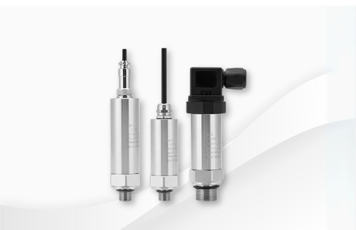
Anwoll is a leading developer of pressure measurement and applications, with a mature series of pressure transmitters suitable for daily and cutting-edge applications.
If you would like to learn more about our pressure transmitters, please contact us directly.

ANWOLL USA
5634 GRAND FLORAL BLVD HOUSTON TX 77041-5561
ANWOLL MEX
Perif. Blvd. Manuel Avila Camacho 1994, Int 203 San Lucas Tepetlacalco, 54050, Tlalnepantla, México
www.anwoll.com.mx
ANWOLL TECHNOLOGY (THAILAND) COMPANY LIMITED
Chachoengsao TFD2 Industrial Estate
ANWOLL actuators include standard actuators, spring-return actuators for the fire industry, and electric ball valves…
ANWOLL monocrystalline silicon differential pressure transmitter has high precision and high sensitivity. - The first…
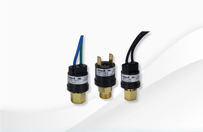
Differential pressure switches generally play a protective role in monitoring targets in equipment. ANWOLL has…
Flowmeters are mainly used in natural gas and petrochemical industries to monitor the flow status…
Includes carbon monoxide, carbon dioxide concentration detection products.
HVAC includes actuators, gas monitoring, wind speed, differential pressure gauges and other products.
The pressure gauge mainly monitors the gas type.
ANWOLL has a wide range of pressure switches to meet the needs of all industries.…
Pressure transmitter is a product commonly used in various industries. Because of different pressure sensing…
ANWOLL has developed wall-mounted, split and duct models for different installation environments.
Thermostat product brand is mainly used for pipe temperature monitoring in the refrigeration industry.
Various wind speed measurements for ventilation ducts.
© 2024 ANWOLL INDUSTRIES INC